We’re excited today to announce that our magnetic encoder modules are finally ready to go!
We’ve been working on these since late last year, and though it took longer than we expected we’re happy to finally be able to offer an easy and powerful solution for bringing closed-loop control to 3D printing.

What do these modules do? Well, mount one of these to a moving carriage on your 3D printer and it will accurately keep track of its position. At first blush that doesn’t sound overly exciting – but what it means is that we can now start to implement closed-loop control at a firmware-level on the printer’s control board.
This means that a lot of things that used to be problems – things like skipped steps, for instance – are no longer problems. Now, if you have a printer that’s skipping the occasional step – maybe it’s an overheating stepper driver, maybe your motor just doesn’t have enough torque, maybe the nozzle snagged on a part of the print – that skipped step will still happen. The cool thing here is that with these modules, the printer will correct the mistake and adjust the affected axis accordingly. Here’s an animation showing this mechanism in action:
In this example, we’ve configured one of the stepper drivers to be overheating – causing the X axis to pause as the driver shuts down intermittently. You can see that when this problem occurs, the nozzle becomes misaligned with the print. Usually this would mean the entire print is ruined – the rest of the print is going to be out of alignment, at best you have a part with a visual defect, and at worst you have a part that’s completely non-functional. For small prints that may not be such a big deal – when you’re talking an hour or so and next to nothing in material costs, you can brush it off. Skipped steps in larger prints can be a whole other thing – discovering that an axis skipped a few steps halfway through a thirty-hour print is not a very nice feeling.
Using the magnetic encoders the problem still occurs, but its impact is limited. The printer knows immediately that the axis is out of place, and moves it back into position. There may still be a visual surface-defect if the nozzle erroneously moved outside the part, but all the subsequent printing takes place as it was meant to.
We did a comparison print with the error-correction functionality disabled. Everything else was unchanged – the exact same hardware, same G-Code file, same stepper driver and same overheating problem. Here’s a photo showing the two:

On the left is the model printed with error correction enabled. The stepper driver overheated a bunch of times – using the error-counting functionality in our Marlin fork, we counted over two-hundred distinct errors greater than 1mm in this print. Errors may still show up as surface blemishes, but they don’t accumulate as the print progresses.
On the right is the same model, printed with error correction disabled. It’s easy to see that every time the stepper driver overheats the print is impacted pretty significantly – the errors do accumulate here, and once an error occurs it’s pretty likely that the print is going to be unfit for purpose.
Neither print looks good. In either scenario, it’s clear that there’s a problem that needs to be addressed. Without error correction, the print is a complete failure – it’s unfit for purpose, and really can’t be salvaged. With error correction it’s a whole different story – the part may not be the prettiest, but odds are it’s still as functional as it needs to be.
Now, these prints were done as a worst-case scenario – the stepper driver was being run way too hot, and it actually took us quite a while to tweak it to this level of bad-ness. There were a lot of problems here, and in real-world scenarios a stepper driver that’s been even vaguely calibrated should never be running hot enough for this to happen – but it’s a fun test case, and shows how powerful error-correction can be.
There are a lot of different ways to approach adding feedback / closed-loop control to 3D printing, and we’ve weighed up as many options as we could think of. We believe that the approach we’ve taken with these modules allows for the most modular and incremental path to full closed-loop control, while still offering a pretty powerful solution straight away. The control system here is basic, but it’s handled by the printer’s firmware – and that means that improvements can be made without replacing the encoder hardware or firmware – for instance, we added the error-counting functionality to Marlin specifically for these tests, well after the encoder firmware had been finalised. It also means that, long term, other encoder solutions could take advantage of the printer firmware, without re-inventing the wheel each and every time.
What do I need?
If you’re interested in giving this system a go, there are a few things you’ll need to get up and running. You’ll need a magnetic encoder module and suitable magnetic strip for each axis you want to modify. You’ll also need some solution for mounting the two in place.
You’ll need printer firmware that supports these new encoders – we have a modified fork of Marlin you can find out about here that does the job.
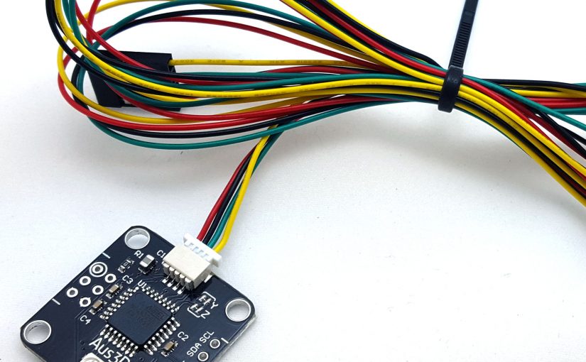
Each encoder module comes with a 1m long cable, and these cables are compatible with RAMPS with no modifications needed – you can plug an encoder module straight into RAMPS.

If you’re not using RAMPS, you may need to change the order of the pins in the cable or otherwise modify the cable. We’ve got wiring images for a bunch of different control boards here.
If you’re using more than one encoder, you’ll need a splitter board. Each splitter board comes with a length of ribbon cable that will go from RAMPS (or other control boards) to the splitter, and that’s all you should need for wiring in most cases.

Our recently released RUMBA+ control boards have headers for up to four encoder modules and can be used without any splitter – so at the moment that’s our absolute tidiest – albeit most expensive – option.
Technical Specs?
When paired with the magnetic strips we’re carrying, these encoder modules have a resolution of 0.480µm. Your average stepper motor, at 200 steps/revolution, running on a 20-tooth GT2 pulley and 1/16th microstepping, has a resolution of 12.5µm – so these modules will quite happily out-resolve most printer axes.
These modules will maintain solid tracking at speeds up to 360mm/s – that’s the highest we’ve been able to test on our printers here, simply considering axis length and acceleration limits – never mind trying to print. The theoretical maximum speed these modules can handle is 400mm/s – but it’s probably a good idea to leave a little breathing room.
The magnetic strips we’re carrying are 300mm long – we recommend leaving at least 5mm on each side of the strip beyond the axis limits, so that means a maximum axis length of 290mm. We’re looking into getting longer (and shorter) strips, but these should be a good starting point – and they can be cut down if needed.
These modules communicate over I2C with the printer control board, and you can add as many to the I2C bus as you’d like. Their I2C address is fully configurable – addresses 30-34 can be selected by cutting traces on the board, and any other valid address can be specified over I2C.
Source?
In the spirit of the RepRap project, these modules are fully open-source – both hardware and software. You can grab the source from our repository here.
Our additions to the Marlin firmware are housed in a separate repository here.
More Information?
We’ve written up a bunch of information on getting these modules set up and running on the wiki page here. We’ll keep adding more information as questions come up, and if you have a question that isn’t answered there just ask us and we’ll get it figured out!
Awesome project! I’ll definitely consider some of these for my larger printer project. Large prints are big time commitments and recovering from a minor glitch early on could still give a useable result. I think this is a good direction for RepRap style printers to develop in.
Rather nice,
one question though, would proximity to stepper motors be an issue?
and how close to the strip does the sensor need to be?
Are these encoders still manufactured ?
I would like to buy several
I know the vendors of the IC you used disappeared but TE has a KMA36, would it work?