RUMBA+ is one of our most popular products, and in the two years since we first launched it, we’ve had a great deal of customer feedback. Today, we’re announcing an updated version based on this feedback, and a reduction in price too!

When we set out to manufacture our own 3D printer control board, our goal was to build something that was both reliable and capable. We wanted something that was easier to use and configure than the common RAMPS setup – so we selected the existing RUMBA design, as it provided all the functionality of RAMPS – and more – in a single board.
However, there were problems with the original RUMBA design, and we wanted something that would be really solid – so we overhauled the design (blog post), and created RUMBA+.
RUMBA+ has served us well since then, and we’ve been really happy with the reception these boards have received. We’ve also been impressed with the feedback we’ve received from the community, and we’ve been taking that onboard as best we can.
Over the past two years, we’ve made several small revisions to RUMBA+. Today, we’re releasing our latest v1.4 boards, and we thought the changes are significant enough that it was worth discussing them.
We spent some time analysing the feedback we’ve received over the past two years, and extracted the five most-common comments that were raised. Obviously, not everyone raised the same issues in the same way, but we’ve tried to group feedback as best we can. Anyway, in no particular order, here are the most common things we’ve heard:
- The USB / Stand-Alone power-select jumper is confusing.
- The power input screw terminals are fiddly, and I had trouble fitting in thick wires.
- I want to use a heated bed that draws more than 15A, but that’s the limit of the screw terminals.
- The miniUSB connector feels fragile or I have broken off the mini USB connector.
- No complaint, but I wish it was cheaper.
With this feedback in mind, we set out to overhaul RUMBA+. Here’s how we’ve addressed each of these points:
1: Confusing Power-Select Jumper
This was the most common issue people raised with us. Occasionally, we’d have a report from someone who thought their board was dead, only to realise that they just needed to set this jumper correctly – not a fun feeling for someone who’s just bought a new control board!
The USB / Stand-Alone Power-Select jumper is a ‘feature’ inherited from the original RUMBA design. It allows the user to select which voltage source they want to feed the board’s 5V logic rail; 5V from USB, or 5V from the onboard regulator. Of course, if the jumper is set to one position, and that power source isn’t present, then the board won’t power up. We default the jumper to the USB position, but that means that any customer who is running without a USB host starts off with a board that won’t power up until they read the documentation.
The manual jumper might not have been a bad way of doing it in the original design, but it’s definitely possible to do better. We’ve removed the jumper, and replaced it with a low-drop OR-ing diode setup – which means, whether you have USB power, 12/24V, or both, the board will always be powered on, and there’s no configuring to do.

2&3: The Power Input Terminals are Fiddly + 15A Heated Bed Limit
The first part here seemed to come up more commonly with people who are using heavier gauges of wire – reporting that it was tough to get the wire inside the terminal easily. That said, we did have a few reports even from people using relatively modest 14AWG that they found the terminals frustrating. These reports overlapped a little with the second – that the 15A rating on the screw terminals was sometimes insufficient for the more extreme builds people had in mind.
We’ve upgraded the main power in, bed power in, and bed power out terminals from basic screw terminals to a higher quality part with improved specifications. The new screw terminals open up wider, suit a wider range of wiring sizes (10-20AWG), and are rated up to 20A.
The MOSFET, board, and screw terminal will happily handle up to a 20A bed, but we’re still shipping with 20A fuses – if you’re playing with a bed right on that limit, you might want to swap in a 25A+ fuse.

4: The mini USB Connector is Fragile
Okay, so this is pretty much a universal complaint about miniUSB connectors – particular in PCB-only products like these control boards. Google is rife with examples – SMD mini USB connectors are designed to be reinforced by the enclosure of whatever product they’re in, and as a stand-alone option are pretty easy to snap off.
We’ve actually only had one customer report damage (and provided an exchange in that case), but we’ve had a number of people raise this concern.
We’ve also had a few reports that it’s possible to pull the USB cable out of the connector without too much effort. Obviously, we’d recommend that all cables be mounted securely so that they can’t be dislodged during a print, but for those who like to live dangerously this can pose a problem.
So, we decided to swap over to micro USB connectors instead. They feature reinforcing ‘tabs’ that mount to plated holes in the board, giving them a lot of extra strength over the older connectors. Additionally, the micro USB connectors are latching, making it harder to accidentally yank the cable.
MicroUSB cables also seem to be a lot more common than miniUSB cables – so it should be easier for people to grab a suitable cable and get up and running.

5: I Wish RUMBA+ Was Cheaper
We’ve heard this a few times. It’s a tricky thing to reply to – we price the boards as best we can, given the costs we have to pay. We want them to be cheaper too, but we can’t sell them at a loss, either.
So, we’ve done two things to address the cost. The first thing we did was to take a thorough look at the boards, and see if there’s anywhere we’re over-spending on things.
One item stood out – the MOSFETs we are using for the HotEnd heaters and fans are massive overkill. They’re the same MOSFETs we’re using for the heated bed, and they could probably handle 30A without breaking a sweat – but of course, the screw terminals they hook up to are only rated for 10A, and even hefty 40W cartridge heaters only draw ~ 3.5A at 12V (and less at 24V). They’re the same MOSFETs as the bed to keep things simple from a logistics perspective, but they’re not a cheap part – so we’ve swapped them to a part that is slightly cheaper, but still well up to the task.
We also overhauled the 12V regulator. The design was built around the LM2596 regulator, which is getting a bit long-in-the-tooth now and is not the most efficient nor cheapest option out there – so we swapped it over to a newer part, improving the current-handling, and were able to shave a little off the cost there, too.
The second thing, actually, we didn’t do – you guys did. We’ve been selling enough of these boards that we’ve recently been able to step up our production volume, lowering our per-board costs – not hugely, but a noticeable amount. That’s all thanks to you guys, our great customers – thank you.
Because of these two cost-reducing measures, we’ve been able to lower the price of RUMBA+ from $169.95 to $149.95, a $20 saving. We hope this makes RUMBA+ a more attractive option for those with stricter budgets.

Now, those aren’t the only improvements we’ve made, but they are the main ones. We maintain a full list of versions and changes on GitHub, here.
New Documentation
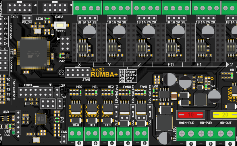
We’re updating our RUMBA+ documentation in line with the new boards. We get a lot of questions about wiring, what currents things are rated to, and so on – so we’ve put together a graphic to try and answer these common questions:
We’re in the process of updating the store page, documentation, and GitHub repo to reflect these new RUMBA+ boards, and should have these resources updated and tidied shortly.
We’d like to thank everyone that’s bought a RUMBA+ board over the last two years – and also everyone who’s trusted us with their business, in general. Without your support, we wouldn’t be able to do product-design work like this – so sincerely, thank you!
As of today, RUMBA+ v1.4 is in stock and ready to go. We’re confident that between the improvements we’ve made and the reduced price, RUMBA+ is now a better option than ever! So, if you’re after a new control board – check the store page.
Thanks for reading!
Does this eliminate the typicals RAMPS sandwich setup? Does the Marlin firmware take all the tweaked setup? i.e. extra steppers for additional extrusion. Can the board run 2 cooling fans on dual extruder and a 3rd cooling fan on the print job, is that part of the 5x PWM outputs? Is the Stepper motor power controlled in firmware? sorry for the questions I’m coming from an old RAMPS sandwich setup and everything is very manual process. thanks, Ryan
Hi Ryan, thanks for your interest!
Yes, the RUMBA+ setup replaces the RAMPS sandwich (good description!) with a single board, except for the stepper driver modules – which are still user replaceable.
Marlin works very well with the RUMBA board, and Marlin includes pre-configured settings for RUMBA – so the main thing that needs doing is setting the board type to RUMBA in the firmware configuration. I’ve just added a quick note about doing this to the RUMBA+ wiki page.
Your setup (I think 1 bed, 2 heater cartridges, 3 fans, all independently controlled) is definitely doable – you’re right, the fans and heaters are the PWM outputs. By default, Marlin configures RUMBA for 3 heater cartridges and 2 fans, but getting it to do 3 fans instead is not a problem – if you shoot us an email I can give you a proper write-up on that.
Stepper motor current/power is still manual, as it is on RAMPS – so it’s still set using the potentiometers on the drivers. We’ve considered changing to software-controlled current, but there aren’t enough pins on the ATmega2560 to do it – so we’d have to remove one of the drivers, or cut something somewhere else. Software-controlled current also requires stepper drivers that are compatible with that setup – there are a few out there, but they tend to be a bit pricier.
I hope that answers your questions! Let me know if there’s any other info you’re after and I’ll see what I can do. If you’d like specific instructions on getting set up, shoot us an email/message and I’ll get back to you.
Hello, my name is Genaro, I´m from Argentina. My question is:
How can i do to conect Filament Runout Sensor ? I should be use pin of Z+?
Thanks!!